
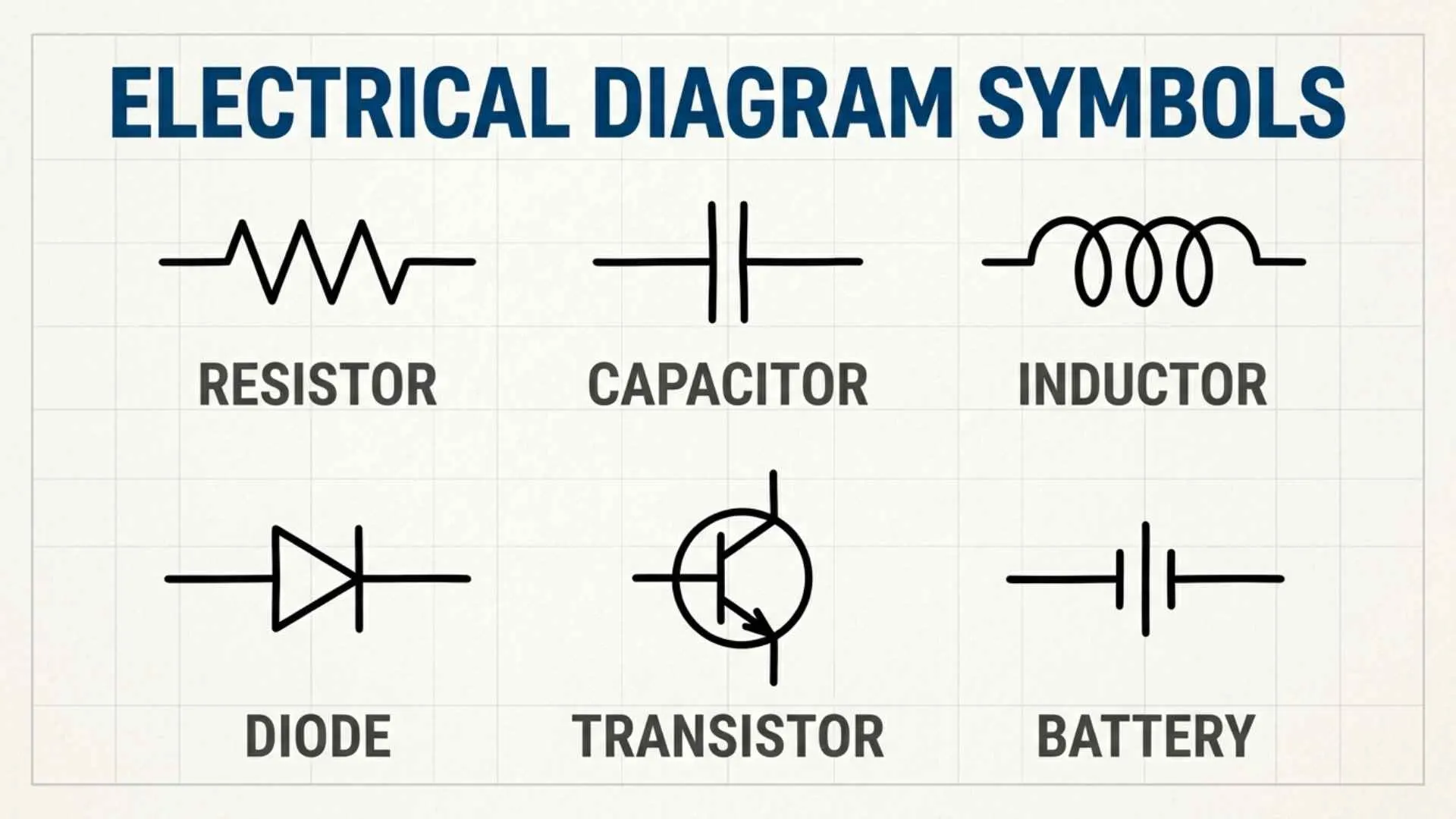
Electrical diagram symbols make it easier to understand how electrical systems and circuits work. Instead of drawing every component in detail, engineers, electricians, technicians, and students use standardized symbols to represent wires, switches, resistors, batteries, motors, and other electrical parts. These symbols create a common visual language that helps people read circuit diagrams, identify components, and understand how electricity flows through a system.
Learning electrical symbols is an important step toward reading wiring diagrams, electronic schematics, and industrial control drawings with confidence. For example, a resistor symbol represents resistance, a battery symbol indicates a power source, and a switch symbol shows where a circuit can be opened or closed. Other symbols represent grounding, fuses, capacitors, transformers, relays, and circuit breakers. Although some symbols vary between standards or regions, understanding the most common ones makes electrical diagrams much easier to follow.
In this complete guide to electrical diagram symbols, you will discover the meanings of common electrical and electronic symbols, their uses, and how they appear in different types of circuit diagrams. You will also learn how to recognize power supply symbols, wiring connections, protection devices, and control components. Whether you are a beginner, an electrical engineering student, a DIY enthusiast, or a professional looking to refresh your knowledge, this guide will help you interpret electrical diagrams more accurately and confidently.
Quick Answer
Electrical diagram symbols are standardized graphic marks used to represent components, connections, devices, and electrical functions on circuit diagrams. They identify items such as batteries, resistors, switches, motors, transformers, grounds, and wires, allowing engineers, electricians, technicians, and students to understand how a system is connected and operates.
Quick Facts About Electrical Diagram Symbols
| Aspect | Information |
| Origin | Developed alongside electrical science and telegraph systems during the 18th and 19th centuries |
| Historical Significance | Made it possible to document, reproduce, repair, and expand increasingly complex electrical systems |
| Main Meaning | Each symbol represents a component, connection, control, or electrical function |
| Spiritual Meaning | They have no formal spiritual meaning, though people may use circuits as metaphors for energy, connection, and balance |
| Cultural Importance | They support global engineering, manufacturing, construction, communication, and technology |
| Modern Usage | Used in schematics, wiring diagrams, control panels, electronics, automotive systems, and industrial automation |
What Are Electrical Diagram Symbols?
Electrical diagram symbols are simplified drawings that stand for real electrical or electronic components. Instead of drawing a realistic light bulb, battery, motor, or switch, a designer uses a recognized symbol.
These symbols appear in several types of technical drawings:
- Circuit schematics
- Wiring diagrams
- Single-line diagrams
- Ladder diagrams
- Block diagrams
- Printed circuit board documentation
- Automotive wiring plans
- Building electrical plans
The idea developed as electrical science became more advanced. Early researchers could describe simple experiments in words, but this became impractical once systems included many wires and devices.
During the 19th century, telegraph networks, electric lighting, motors, and power distribution created a need for clear technical documentation. Engineers began using graphic marks to show how components were connected.
Over time, professional organizations created standards to reduce confusion. Today, common symbol systems are influenced by organizations such as the International Electrotechnical Commission, or IEC, and the Institute of Electrical and Electronics Engineers, or IEEE.
Symbols may look slightly different under IEC, ANSI, British, European, or regional standards. However, their basic functions usually remain recognizable.
Why Electrical Diagram Symbols Matter
A circuit diagram is more than a picture. It is a map of electrical behavior.
A trained reader can examine a diagram and determine:
- Where electrical power begins
- Which path the current follows
- What controls the circuit
- Which devices use electrical energy
- How components are protected
- Where the circuit returns or connects to ground
This shared visual language also improves safety. An electrician repairing a control panel does not need to guess what each wire does. The diagram shows the intended connections and operating sequence.
Clear symbols also help engineers design systems before physical equipment is installed. Mistakes can be discovered on paper or in software, where they are far easier and less costly to correct.
Deep Symbolic Meaning of Electrical Diagram Symbols
Electrical symbols are technical tools, not sacred or mystical signs. Still, their visual language can carry metaphorical meaning when viewed through psychology, philosophy, or art.
Spiritual Level
There is no official spiritual interpretation of a resistor, capacitor, battery, or switch. Any spiritual meaning attached to these marks comes from personal reflection rather than electrical science.
A closed circuit may symbolize completeness because energy has a continuous path. An open switch may represent separation, pause, or unrealized potential. A ground symbol may suggest stability, safety, or connection to the earth.
These comparisons are poetic rather than technical. They should never replace the actual engineering meaning of a symbol.
Psychological Level
Humans naturally search for order in complicated information. Electrical diagrams satisfy that need by turning invisible electrical activity into visible patterns.
From a psychological perspective, symbols reduce mental effort. A familiar resistor symbol communicates information faster than a written paragraph describing a resistance component.
Carl Jung wrote about archetypal images shared through human experience. Electrical symbols are not Jungian archetypes in the traditional sense, but circles, lines, crossings, and arrows can still trigger familiar ideas such as movement, connection, direction, interruption, and transformation.
Cultural Level
Electrical symbols represent a culture built around scientific cooperation. A technician in one country can often understand a diagram created in another because both rely on established conventions.
This makes the symbols part of a global technical language. They connect education, infrastructure, transportation, medicine, manufacturing, and communication across national borders.
Types and Variations of Electrical Diagram Symbols
Wire and Connection Symbols
A straight line usually represents an electrical conductor or wire.
When two wires join, the connection is commonly marked with a solid dot. When lines cross without a dot, they may not be electrically connected. Some standards use a small bridge or curved jump to make the separation clearer.
These marks appear in nearly every circuit diagram because they show the paths through which current can travel.
Cell and Battery Symbols
A cell is usually drawn as one long parallel line beside one shorter line. The longer line represents the positive terminal, while the shorter line represents the negative terminal.
A battery is represented by multiple pairs of long and short lines. It supplies electrical energy to the circuit.
The symbol reflects the historic structure of electrochemical cells and remains one of the most widely recognized electrical marks.
Resistor Symbols
A resistor limits current or creates a voltage drop.
In many American diagrams, it appears as a zigzag line. IEC diagrams often show it as a rectangle. Both forms represent the same basic component.
A variable resistor includes an arrow touching or crossing the resistor symbol. It represents an adjustable resistance value.
Capacitor Symbols
A capacitor stores electrical charge. Its basic symbol has two parallel plates separated by a gap.
A polarized capacitor may include a plus sign or one curved plate to identify polarity. Connecting a polarized capacitor backward can damage the component or create a safety risk.
Capacitors appear in filters, power supplies, timing circuits, motors, and electronic devices.
Inductor Symbols
An inductor is usually shown as a series of curved loops or coils. It stores energy in a magnetic field when current flows through it.
Inductors are used in filters, transformers, power converters, radios, and motor-control systems.
Switch Symbols
A switch controls whether a circuit path is open or closed.
A basic open switch is drawn as a break in a conductor with a movable contact angled away from the other terminal. A closed switch shows the contacts touching.
Common variations include:
- Push-button switches
- Toggle switches
- Limit switches
- Selector switches
- Normally open contacts
- Normally closed contacts
In industrial ladder diagrams, normally open and normally closed contact symbols are essential for understanding control logic.
Lamp and Light Symbols
A lamp is commonly drawn as a circle containing a cross or filament mark. It converts electrical energy into light.
Modern drawings may use separate symbols for incandescent lamps, indicator lights, light-emitting diodes, and other lighting devices.
Diode and LED Symbols
A diode permits conventional current primarily in one direction. Its symbol includes a triangular or arrow-like directional form in some related devices, but the standard semiconductor diode is represented by a triangle-free directional line arrangement ending at a vertical bar.
An LED uses the diode symbol with two small arrows pointing outward. These arrows represent emitted light.
Photodiodes use arrows pointing inward because they respond to incoming light.
Transistor Symbols
Transistors control or amplify electrical signals. Bipolar junction transistors are commonly identified as NPN or PNP.
Their symbols include three terminals:
- Base
- Collector
- Emitter
The emitter arrow helps distinguish the type. A common memory aid is that the NPN arrow points outward, while the PNP arrow points inward.
Transformer Symbols
A transformer is shown as two or more coils placed near each other. Parallel lines between the coils may represent a magnetic core.
Transformers transfer electrical energy through electromagnetic induction. They can raise voltage, lower voltage, provide isolation, or match electrical characteristics.
Motor and Generator Symbols
A motor is often represented by a circle containing the letter “M.” It converts electrical energy into mechanical motion.
A generator may use a circle containing the letter “G.” It performs the reverse process by converting mechanical energy into electrical energy.
Fuse and Circuit Breaker Symbols
A fuse protects a circuit by melting when current becomes dangerously high.
A circuit breaker also interrupts excessive current, but it can usually be reset. Symbol designs vary between building plans, industrial schematics, and single-line power diagrams.
Ground and Earth Symbols
Ground symbols may identify different reference points.
The earth ground symbol commonly uses three horizontal lines that decrease in width. A chassis ground may use angled lines, while signal ground may appear as an inverted triangle.
These symbols are not always interchangeable. The correct ground reference matters for safety, noise control, and circuit operation.
Electrical Diagram Symbols Across Different Cultures and Standards
Ancient Egypt
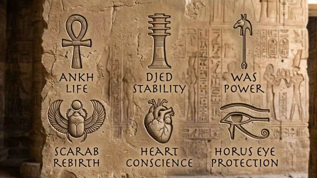
Ancient Egyptians did not use electrical diagrams in the modern engineering sense. Claims that Egyptian reliefs show electric lamps are not accepted by mainstream archaeology.
However, Egyptian hieroglyphs demonstrate an early human ability to communicate complex ideas through standardized visual signs. This symbolic tradition is conceptually similar to the way modern engineers use graphic marks.
Ancient Greece
Greek thinkers studied matter, magnetism, and static electricity. The word “electricity” is connected to the Greek word elektron, meaning amber.
The Greeks did not create circuit symbols, but their observations helped begin the intellectual path toward electrical science.
Roman Culture
Romans developed advanced systems for roads, water, buildings, and mechanical devices. Although they did not use modern electricity, their engineering culture emphasized plans, measurements, and repeatable construction.
That practical tradition influenced later European technical drawing.
Eastern Traditions
Chinese discoveries related to magnetism and the compass contributed greatly to scientific development. Later, Japan, China, South Korea, and other Asian nations became leaders in electronics and manufacturing.
Modern electrical drawings in these regions commonly follow IEC-based conventions, though local documentation practices may differ.
Indigenous Traditions
Indigenous cultures did not historically use standardized electrical schematics. However, many developed rich visual languages for navigation, storytelling, land knowledge, astronomy, and community memory.
These systems remind us that symbols are powerful because communities agree on their meaning.
Modern Interpretations
Today, electrical diagrams are global documents. IEC symbols are widely used internationally, while ANSI and IEEE traditions remain common in North America.
Engineers must check the drawing legend and applicable standard instead of assuming every symbol has one universal form.
Similar Symbols and Their Meanings
| Symbol Type | What It Represents | Common Confusion |
| Cell | One source of electrical energy | Often called a battery |
| Battery | Two or more cells | Sometimes used loosely for a single cell |
| Earth ground | Physical connection to earth | Confused with signal or chassis ground |
| Resistor | Fixed resistance | Confused with a heating element |
| Variable resistor | Adjustable resistance | Confused with a potentiometer |
| Capacitor | Charge-storage component | Polarized and nonpolarized forms may be mixed up |
| Open switch | Broken current path | Some readers assume it shows a faulty switch |
| Normally closed contact | Closed in its normal state | “Normal” refers to the unactivated condition |
Electrical Diagram Symbols in Mythology and Folklore
Electrical diagram symbols do not appear in ancient myths because electrical engineering is a modern discipline. However, electricity itself has often been connected with mythological ideas.
Lightning was associated with divine power in many cultures. Zeus controlled thunderbolts in Greek mythology, while Jupiter held a similar role in Roman tradition. Thor carried thunder symbolism in Norse stories.
Modern electrical symbols transformed this once-mysterious force into something measurable and controllable. In that sense, the circuit diagram marks a cultural shift from explaining electricity through divine stories to describing it through science.
Electrical Diagram Symbols in Art, Literature, Movies, and Pop Culture
Circuit patterns often appear in science fiction, digital art, clothing, tattoos, movie interfaces, and technology branding.
Artists use circuit lines to represent:
- Intelligence
- Artificial life
- Human connection
- Digital identity
- Hidden systems
- Futuristic power
- Communication networks
Movies often display complex circuit diagrams to make laboratories, robots, spaceships, or control rooms feel technically advanced. These images may not always be electrically accurate, but they communicate ideas of knowledge and technological control.
Circuit-board designs are also popular in tattoos and fashion. They may symbolize a logical mind, love of technology, personal transformation, or the connection between people and machines.
Spiritual and Dream Meaning of Electrical Diagram Symbols
Dreaming about a circuit or electrical diagram may reflect thoughts about connection, energy, control, or problem-solving. However, dream interpretation is subjective and is not a scientific diagnostic method.
A complete circuit might suggest that different parts of life feel connected. A broken wire could represent interrupted communication. A short circuit may reflect emotional overload, stress, or conflicting responsibilities.
These meanings depend on the dreamer’s experiences. An electrician may dream about diagrams simply because they are part of daily work.
Positive and Negative Meanings of Electrical Diagram Symbols
| Positive Meaning | Negative Meaning |
| Connection | Disconnection |
| Order | Confusion |
| Energy flow | Overload |
| Communication | Signal failure |
| Safety and control | Electrical danger |
| Innovation | Dependence on technology |
| Problem-solving | Technical frustration |
The same image can represent both light and shadow. A connected circuit may suggest cooperation, while a damaged circuit can symbolize isolation. Context determines the emotional meaning.
Why Humans Are Attracted to Electrical Diagram Symbols
People are drawn to electrical diagrams because they reveal an invisible world.
Electric current cannot normally be seen moving through a wire. A schematic gives that hidden process a visible structure. It turns energy into lines, decisions into switches, resistance into components, and movement into paths.
The brain also enjoys solving patterns. Following a circuit from its power source to its load can feel like solving a puzzle. Each symbol becomes a clue.
For engineers and technicians, the attraction is practical. For artists and technology lovers, the symbols may represent modern intelligence, connection, and possibility.
Modern Uses of Electrical Diagram Symbols
Electrical symbols remain essential in many fields:
- Residential wiring: Outlets, lighting, switches, panels, and protective devices
- Industrial automation: Relays, contactors, sensors, motors, and programmable controllers
- Electronics: Diodes, transistors, integrated circuits, capacitors, and logic gates
- Automotive systems: Batteries, alternators, fuses, sensors, lighting, and control modules
- Renewable energy: Solar panels, inverters, batteries, disconnects, and grid connections
- Telecommunications: Signal paths, amplifiers, antennas, and communication equipment
- Medical equipment: Power supplies, monitoring circuits, sensors, and safety systems
- Education: Teaching circuit theory, electronics, physics, and troubleshooting
They also appear in branding, social media graphics, home decor, clothing, jewelry, and personal artwork.
Interesting Facts About Electrical Diagram Symbols
- The resistor may appear as a zigzag line or rectangle, depending on the standard being followed.
- A dot at a wire crossing usually indicates a connection, but older diagram styles may use different conventions.
- The ground symbol can represent earth ground, chassis ground, or a circuit reference, which are not always the same thing.
- Normally open and normally closed contacts are named according to their unpowered or unactivated state.
- Schematics show electrical relationships, not the real physical positions of components.
- Wiring diagrams usually focus more on actual terminals, wire colors, and physical connections.
- A single-line diagram can represent a three-phase power system using one main line.
- Many electrical design programs include symbol libraries based on IEC, ANSI, or industry-specific standards.
- Diagram legends are important because manufacturers may use specialized or modified symbols.
- Understanding symbols is only the first step. Safe electrical work also requires training, testing tools, protective equipment, and knowledge of applicable codes.
Frequently Asked Questions
What are the most common electrical diagram symbols?
The most common symbols represent wires, batteries, switches, resistors, capacitors, diodes, lamps, motors, transformers, fuses, circuit breakers, and ground connections.
Are electrical symbols the same in every country?
Not always. IEC symbols are common internationally, while ANSI and IEEE conventions are widely used in North America. Always check the drawing standard and legend.
What is the difference between a schematic and a wiring diagram?
A schematic shows how a circuit works electrically. A wiring diagram focuses more on physical connections, terminals, wire identification, and installation details.
What does a dot on crossing wires mean?
A solid dot usually means the wires are electrically connected. Lines that cross without a dot are generally not connected, though older conventions may vary.
Why are some resistor symbols rectangular?
The rectangular resistor is common in IEC diagrams. The zigzag resistor is common in American or ANSI-style schematics. Both represent resistance.
How can I learn electrical diagram symbols quickly?
Begin with power sources, wires, grounds, switches, loads, and protection devices. Then study simple circuits and trace the current path from the source through each component.
Conclusion
Electrical diagram symbols make the hidden movement of electricity understandable. Each line and mark helps people design, build, test, and repair the systems that power modern life. Although the symbols are technical rather than mystical, they still reflect powerful human ideas about energy, order, connection, and control. Learning their language allows you to look at a confusing circuit and discover a clear story inside it.
 Michael Rivera
 John Mercer